

Materials with low thermal conductivities and high compression strengths have become a popular solution for reducing thermal bridging in steel connections that penetrate the building envelope. While thermal breaks help to meet energy code requirements, materials that are not metal are not considered in the AISC/RCSC* bolted, structural connection design specification. What methods are structural engineers using to design connections using thermal breaks?
*Research Council on Structural Connections.
Discussion points:
- AISC and RCSC Design Code
- Material Properties
- Methodology
AISC and RCSC Design Code
So, what design methodology and considerations are structural engineers using when they design a moment connection requiring a thermal break? What justifications are made to protect the structural integrity of the connection design?
In the latest edition of the RCSC, “Specification for Structural Joints Using High-Strength Bolts”, dated June 2020, section 1, General Requirements, states: “This specification covers the design of bolted joints with collateral materials in the grip (of the bolts) that are made of steel. These provisions do not apply when materials other than steel are included in the grip….”
However, the commentary does go on to mention several research projects to investigate the structural properties of thermal break materials as well as an evaluation of several secondary, load-bearing connections using thermal breaks. It has been demonstrated that thermal break materials can show acceptable behavior in the connections that were studied. Additionally, there have also been several papers written on the subject. (see additional references listed at the end of this article)
Where does this leave the structural engineer tasked with incorporating a thermal break into a canopy or balcony element to meet energy code? The AISC* “Specification for Structural Steel Buildings” includes this statement:
“Where conditions are not covered by this specification, designs are permitted to be based on tests or analysis, subject to the approval of the authority having jurisdiction. Alternative methods of analysis and design are permitted, provided such alternative methods or criteria are acceptable to the authority having jurisdiction.”
*American Institute of Steel Construction
Material Properties

Image credit: Steel Construction Institute
Material properties are often used to specify a thermal break material. However, the most important aspect of designing a bolted, steel connection using a thermal break is compression. Will the connection remain ideally rigid and fully restrained? Or, will the thermal break material create additional rotation, prying, and potential bending in the bolts? Will the thermal break material provide any resistance to shear or will the bolts alone be expected to resist the shear force?
The reason the RCSC specification doesn’t allow for compressible materials within the grip of the bolts is that any significant compression due to a moment load decreases rotational stiffness creating additional load (tension) on the upper group of bolts. In shear, compression can reduce bolt shear capacity and create bending.
There are several methods to determine whether the thermal break material is going to compress, given a set of loading conditions. The material properties themselves do not tell you that – the loading conditions are required. While compressive strength indicates the stress at which a material fails, it is the material’s Young’s modulus or modulus of elasticity that is a measure of the material’s resistance to deformation under compression load. The elasticity is calculated by the relationship between stress (load) and strain (deformation).
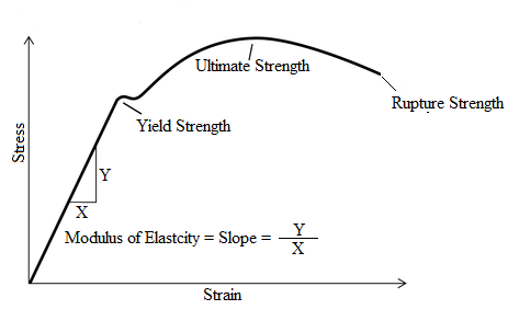
The composite materials offered in the market as thermal breaks for steel connections all have compressive strengths greater than 30,000 psi. Therefore, the stress-strain curves usually show a stress range from 0 – 30,000 psi or 40,000 psi so that the elastic load range or stress/strain response of the material can be developed and shown. From this, Young’s modulus (E) is calculated in a 5,000 or 10,000 psi to 30,000 or 40,000 psi load range using equation (1). Compression can then be calculated using equation (2) where, (t) is the material thickness, (σ) is the stress on the material, and (E) is Young’s modulus of the material at thickness (t).
eq. 1 E = σ/ε eq. 2 δ = t(σ)/E
The higher the modulus (E), the stiffer the material behaves. Under the same stress, a material with a lower modulus undergoes more strain and hence more compression. An assumption when specifying a thermal break material and then considering an “or equal” to that material could be that a lower modulus material won’t be functionally equivalent. However, let us have a look at this assumption.
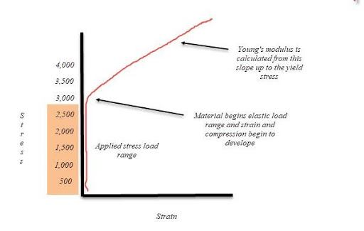
The majority of moment connections using a thermal break create stress on the thermal break material of 2,000 psi or even less. Very rarely does the stress exceed 2,500 psi and in many connections, the stress is as low as 500 psi. These values are quite low when compared to the compressive strengths and moduli of the materials offered in the market.
While the strain and resulting compression of material can never scientifically be zero, at extremely low-stress levels, the strain and compression of composite materials used as thermal breaks, does approximate “zero”. Table 1 shows a generic range of material Young’s moduli and applied stress values with the resultant compression of the materials, calculated using equation 2 above. The results show that even when the difference between two materials compression modulus is double, the largest difference in compression is only 5 mils (0.005”) maximum.
Table 1
|
E |
250,000 | 300,000 | 350,000 | 400,000 |
500,000 |
| Stress | |||||
| 500 | 0.002” | 0.0016” | 0.0014” | 0.0012” | 0.001” |
| 1000 | 0.004” | 0.003” | 0.003” | 0.0025” | 0.002” |
| 2000 | 0.008” | 0.0067” | 0.006” | 0.005” | 0.004” |
| 2500 | 0.01” | 0.008” | 0.007” | 0.006” | 0.005” |
Moreover, if we “zoom in” on the stress-strain curve of material, in the range of say 0 – 4,000 psi, we can get a better understanding of what is actually happening in the applied stress range of the majority of moment connections. Note that the strain and hence compression is insignificant until approximately 2,500 psi, at which point the material begins its elastic range and strain and compression begin to develop.
One could argue that the point on the curve where strain and compression begin to develop should be characterized as the allowable stress or limit state for the material since higher, stresses will only serve to create larger compression values (eq.2). Yet, the compression values calculated in Table 1, are taken from Young’s modulus which is calculated at stresses much higher than this point.
This begs the question for structural engineers and designers: What value of compression in a thermal break material should be considered significant or meaningful in bolted, steel connections?
A method or check is also required to validate the shear capacity of the bolts when a thermal break is installed, which increases the length of the grip. The shear modulus and shear strength can be used to calculate resistance and compression due to shear load which can then be used to check for bending and any reduction in shear capacity of the bolts.
Lastly, the creep properties of the thermal break material should be considered. Creep is expressed as a function of initial and total deformation and is often defined as “permanent deformation under long term and high levels of stress.” At stresses above 10,000 psi, additional, significant compression can occur due to long-term creep. However, at stresses below 2,500 psi, compression is insignificant and therefore any potential creep is as well. For applied stresses higher than 2,500 psi, creep should be given careful consideration as it could create a loss in bolt force and loss of pretension.
Methodology

Image source: Steel Construction Institute
The composite materials used as thermal breaks in bolted, bearing connections with moment, and shear loading are more compressible than steel. Therefore, in addition to the code-required checks, whether using the ASD or LRFD approach, the following should be considered in the structural design method used.
- Tension, moment, and shear forces
- Stiffness characteristics of the thermal break material (compression resistance)
- Connection rotational stiffness
- Long term creep potential of thermal break material
- Reductions in the sheer capacity of the bolts
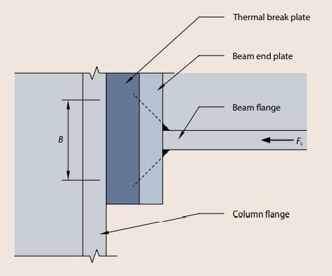
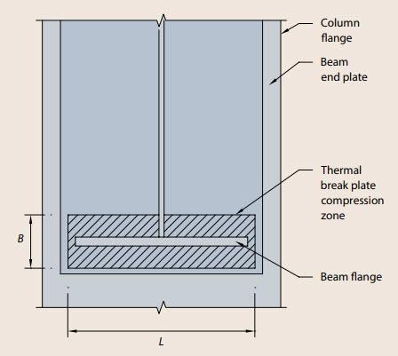
To check for compression in the thermal break material due to a moment load, at least two methods can be used; Finite Element Analysis or the SCI method. Using FEA the resultant stresses and deformations in a connection are readily produced. Using the SCI method, the applied force (Fc) is first calculated from the moment load and then the area of thermal break material upon which the force will be applied is calculated. SCI uses the following equations to determine the area where; (tb) is the beam flange thickness, (s) is the weld length, (tp) is the endplate thickness, and (bb) is the beam flange width.
eq. 3 B = tb+2 (s + tp) eq. 4 L = bb + 2 (tp )
Images source: Steel Construction Institute
From the area and force, the stress and resultant compression on the material can easily be found by either a stress-strain curve or equation 2.
A method to calculate bolt shear resistance when using a thermal break is also necessary. SCI provides a method to British Standards based on the thickness of the thermal break, and if the thermal break material exceeds the thickness limitation, it further offers a method for determining a reduction in shear resistance of the bolts.
Because the compression of the material in shear is typically insignificant, many engineers defer to section J5, para. 2 of the AISC specification, “filler plates” to make a reduction in the shear capacity of the bolts when the “filler” or thermal break exceeds ¼” in thickness. However, it is important to remember that even though the stresses developed on the thermal break are typically very low, the specification does not acknowledge or pertain to materials that are not steel.
A third method uses the shear modulus to determine any compression in shear and the shear strength of the thermal break material to help determine the shear capacity of the connection. The shear strength of the material is useful since the load path is transferred through the bolts, then the material, then the endplate. Conservatively, a fourth method assumes the thermal break does not exist and there is simply an air gap between the endplates where the entire shear load is borne by the bolts.
Many methods can be used to justify the use of a thermal break material in a bolted, steel connection. The justification comes from calculations, not the strength properties of the materials themselves. It has been shown that at low stresses, a wide range of strength properties are actually functionally equivalent, allowing different materials to be used as “approved alternates” to one another.
About the author: Rob Haley developed the first thermal break material used for steel connections (Fabreeka-TIM) in 2012 while engineering manager at Fabreeka International. He was later co-owner of Armadillo NV where he was responsible for the marketing and research and development of Armatherm thermal break materials. He has over 10 years experience with thermal breaks to reduce heat loss due to thermal bridging. email: rob@thermalbridgingsolutions.com

References
Structural Construction Institute, “Thermal Bridging in Steel Construction”, p410
Research Council on Structural Connections, “Specification for Structural Joints Using High-Strength Bolts”, June 11, 2020.
ANSI/AISC, “Specification for Structural Steel Buildings”, July 7, 2016.
Other Resources
Journal of Constructional Steel Research, “Structural performance of axially- and laterally-loaded cantilevers with thermally-improved detailing”, Peterman, Kordas, Webster ,D’Aloisio, Hajjar.
Charles Pankow Foundation, “THERMAL BREAK STRATEGIES FOR CLADDING SYSTEMS IN BUILDING STRUCTURES”, Peterman, et al.