

Thermal Bridging
Energy Conservation
Energy codes regulate the design of buildings with the intent of conserving energy. They seek to improve building energy performance. In the past 15 years, the ASHRAE and IECC energy codes have been revised and rewritten, increasing the required energy efficiency of buildings by almost 40%. In 2012, commercial building energy consumption in the United States totaled 6.96 trillion BTU. In 2018, this figure grew to 9.40 quadrillion BTU¹.
If our energy codes are increasingly reducing the amount of energy a building or home can use, how can energy consumption be increasing? Revising the codes every three years is a necessary, responsible step in the process of reducing energy consumption; however, states and provinces choose how and when they will enforce these codes. For example, some states enforce the 2010 version of ASHRAE 90.1 while others use the 2013 or 2016 version. Twenty percent (20%) of states only enforce versions prior to 2007 or no code at all.
6,960,000,000,000 commercial building energy consumption (BTU) 2012
9,400,000,000,000,000 commercial building energy consumption (BTU) 2018
11,900,000,000,000,000 residential building energy consumption (BTU) 2018
(Quadrillion = fifteen zeros!)
Energy Codes and Thermal Bridging
For your building or home to be code compliant, which design method or path will you choose? Prescriptive? Performance? Or will your project go beyond code using LEED or Passive House standards?
Using the prescriptive path method in ASHRAE 90.1 will result in a building that meets code but does not necessarily minimize energy consumption.
Using the performance path Performance Rating Method, energy cost is used to evaluate building energy performance. The building is designed to have lower energy costs than its prescriptive twin (based on the 2004 version of 90.1). This method is an accurate way of demonstrating energy cost savings using building energy modeling.
The building envelope is part of the ASHRAE 90.1 and IECC energy codes. Regardless which version of the codes or method you use to achieve code requirements, the impact of thermal bridging on the envelope is largely ignored. To design a truly energy efficient building, you must design to a higher standard.

A building envelope or building enclosure is the physical separator between the exterior and interior environments of a building. The function of the enclosure is to provide resistance to air, water, heat, light, and noise transfer.
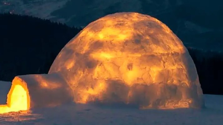
Image credit: Volodymyr Shevchuk
The R values and U factor methods given in ASHRAE appendix A and IECC chapter 5 for typical construction assemblies, do not include the effects of many sources of thermal bridging.* What about masonry shelf angles, cladding attachments and wall-to-foundation transitions that interrupt continuous insulation? These thermal bridging anomalies are not considered in current versions of 90.1 or the IECC, yet it has been demonstrated that these interface details and transitions create substantial thermal bridges.
The 2016 version of 90.1 does require thermal modeling of uninsulated assemblies (balconies, parapets, etc.) to determine their contribution to building envelope heat loss. However, this approach uses area weighted averaging and assumes that heat flows in parallel heat paths. Therefore, in 2018 ASHRAE issued addendum av for public review to specifically address thermal bridging and thermal bridging solutions. However, thermal bridging will not be addressed specifically in the 2019 version of 90.1.
The NECB (National Energy Code of Canada for Buildings) does address thermal bridging as it relates to building energy performance. The technical requirements for energy efficiency in building design include lower U values for roof assemblies and prerequisites for reducing the impact of thermal bridges in all other locations in the envelope.
*The impact of thermal bridging due to steel stud framing has been recognized using a “framing factor” resulting in a more accurate R value for interior cavity insulation values. This realization has resulted in the code requirement for exterior continuous insulation or “C.I.”
The thermal envelope can be defined as the layer of the building enclosure that helps provide conditioned space or provides a boundary between conditioned and unconditioned spaces.
Heat Loss and Thermal Bridging
Thermal bridging and its part in heat loss was a relatively new topic six or seven years ago. Until recently, thermal bridging had been ignored even though it can reduce a wall’s R value by nearly 50%. Adding more and more insulation to a wall or roof to overcome the effects of heat loss due to a thermal bridge has proven ineffective and inefficient.
Of the 9.40 quadrillion BTU consumed by commercial buildings in 2018, space heating consumed the most energy (20%). Building enclosure design is directly related to this energy consumption.
Other than the gains and losses associated with fenestration and mass, the two major contributors to overall enclosure energy loss are air leakage and thermal bridging. Heat transfer due to air leakage is by convection while heat transfer due to thermal bridging is typically by conduction. Minimizing these two helps to a) prevent moist air from entering the thermal envelope and b) prevent material surfaces in the thermal envelope from cooling below the dew point – both of which can cause condensation.
While the contribution of heat loss by thermal bridging can be found through thermal modeling, air leakage is more difficult to define in a model since it lacks thermal conductivity properties. Nonetheless, the importance of air leakage and air barriers to control moisture and heat loss has long been established in building codes and standards like Passive House. Thermal bridging is now being given much more consideration.
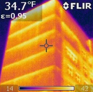
Thermal image showing heat loss at shelf angles within a masonry facade. Image credit: James D’Aloisio, P.E., LEED AP
Is Continuous Insulation Really Continuous?
It is recognized that the thermal bridging created by steel stud framing reduces the effective R value of internal cavity insulation by over 40%. Therefore, for a wall assembly to meet energy code, continuous insulation is used on the exterior of the framing to increase the overall R value. The R values and U factors given in ASHRAE 90.1 and the IECC codes account for this using a framing factor and a specified value for “C.I.” However, do you really have continuous insulation in your design? Continuous as defined by ASHRAE means “without thermal bridges other than fasteners.”
What happens when a balcony, masonry shelf angle or Z girt passes through the continuous insulation and thermal layer of the envelope? There is a breach in the boundary, a compromise in the enclosure. In short, a thermal bridge is created.
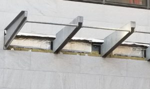
Canopy attachments running through the exterior insulation creating a thermal bridge at each location.
Let’s review. Energy codes recognize that steel studs reduce the thermal resistance of interior wall cavity insulation to the extent that the R values and U values given for various wall assemblies are corrected values based on the heat loss contributed by the studs. Exterior, continuous insulation is then added so that the total assembly effective R value meets energy code.
Why are the other sources of thermal bridging (which reduce the thermal resistance of the continuous insulation) being ignored? How do we account for the heat loss due to these thermal bridges? What do we do in order to meet the continuous insulation requirement?
Modeling and Thermal Bridging
If you are using a performance based design method or beyond-code strategy in your design, energy modeling is a requirement. How much does the thermal envelope performance dictate the overall building efficiency? How sensitive is the whole building energy efficiency to thermal bridging?
Aside from air leakage due to poorly designed or installed air barrier details, heat flow through the thermal envelope is the summation of fenestration U values and wall, roof and foundation U values. Wall, roof and foundation U values are a summation of their clear field U values and any heat loss due to thermal bridges. The most accurate way to determine an assembly’s clear field U value and the heat loss due to thermal bridging is thermal modeling.
The primary benefit of modeling interface and transition details is accuracy. Whether you’re using COMcheck, REScheck WUFI or whole building energy modeling to determine building envelope performance, heat losses due to thermal bridging should be accounted for. This means the R values and U values used as inputs in these software programs should be corrected, effective values.
Simply adding the R values of all of the material components together or using area weighted averaging to account for a thermal bridge yields a misleading result. Why? Heat flows in three dimensions, especially when using highly conductive construction materials. The flow is not parallel, making simple math inaccurate.
Design performance modeling prior to whole building energy modeling helps design teams to evaluate options and prioritize energy saving measures. As part of the early design stage evaluation process, thermal modeling will quantify thermal bridging heat loss and provide more accurate assembly U values.

Image Credit: Morrison Hershfield BETBG, Appendix B, Catalogue Material Data Sheets (Version 1.3)
Three dimensional heat flow at curtain wall mullion connections and sun shade beam connection.

Image Credit: Morrison Hershfield BETBG, Appendix B, Catalogue Material Data Sheets (Version 1.3)
Three dimensional heat flow at curtain wall mullion connections in wall spandrel area
Thermal modeling has revealed, much like the effects of steel stud framing, that masonry shelf angles and steel Z girts, for example, can reduce the R value of a wall assembly by as much as 50%.

Image Credit: Morrison Hershfield BETBG, Appendix B, Catalogue Material Data Sheets (Version 1.3)
Thermal model of wall cladding using metal attachments and concrete floor to balcony transition. Note the cooler temperatures at or behind the exterior sheathing due to thermal bridging.
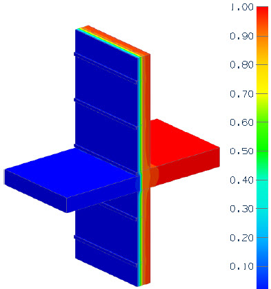
Image Credit: Morrison Hershfield BETBG, Appendix B, Catalogue Material Data Sheets (Version 1.3)
Same thermal model with thermal breaks installed at cladding attachments and concrete balcony. Note the colder temperatures are now located outside of the exterior sheathing.
In modeling, thermal bridges are characterized as “point” or “linear.” Point thermal bridges are discrete connection points such as canopy, balcony or roof screen posts. Linear thermal bridges are defined by length. Shelf angles, parapets and wall transitions are examples. Wall and roof assemblies are modeled with and without the thermal bridging features. This results in a more accurate clear field U value and an adjusted, effective U value for the assembly, which includes the impact of heat loss by the thermal bridge.
What if the effective U value does not meet code? The model can be used to explore the effectiveness of various thermal break solutions. Manufacturers of thermal break materials and systems publish the thermal conductivity and/or R values of their products. These values are assigned to thermal break components in the revised model, and an optimum thermal break solution can be determined.
Aside from lower than assumed R values, thermal bridges that are not addressed can also cause another problem – moisture. In addition to the degree of heat loss, thermal modeling will also indicate the temperature of material surfaces within the thermal envelope due to thermal bridging. This is useful in determining whether condensation is a risk by comparing the surface temperatures to the dew point. Thermal breaks also help to keep surface temperatures that are below the dew point on the outside of the thermal envelope.