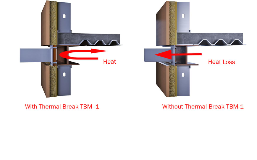
Structural thermal break materials are used to reduce the heat loss associated with thermal bridging in steel connections that pass through exterior insulation. They can also reduce the risk of condensation forming within the wall as the heat loss cools material surfaces below the dew point. How efficient are thermal breaks in steel connections?
Discussion points:
- Thickness, Thermal Conductivity and Heat Flow
- Transmittance and R Value
Thermal Conductivity and R Value
If you are reading this article, you already have an interest in improving the energy efficiency of your building envelope. But what is the first step? Which material do you use? How do you determine the improvement in thermal resistance and successfully reduce the effects of thermal bridging?
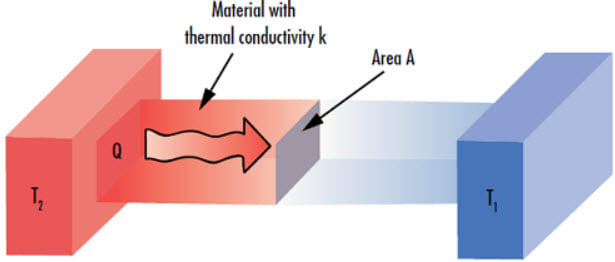
By definition, thermal conductivity (k) is the measure of a material’s ability to transfer heat. To be effective, a material used as a thermal break in a bolted, steel connection must have a thermal conductivity much, much lower than that of steel. The thermal conductivity of a thermal break material is one of the important variables in determining the rate at which heat flows through that material. Heat flow also is dependent on area and temperature.
Does thickness of the thermal break matter? Yes. For all materials, conductance is a function of thickness. Both thickness and area therefore are two more important variables to consider in heat flow calculations for a thermal break material.
Let’s have a look at how these variables work together to create heat flow or to be more specific, heat transfer through a material used as a thermal break. Heat flows from warm to cold when there is a difference in temperature from one side of the material to the other. Equation 1, (Fournier’s law of heat transfer) is used to calculate this flow, where (k) is the material thermal conductivity, (A) is the material surface area, (ΔT) is the temperature difference and (t) is the thickness of the thermal break material.
eq. 1 Q = kA ( ΔT/t)
Two things that are clear from equation 1 are the smaller the temperature difference, the lower the heat flow rate and, the lower the thermal conductivity of the material, the lower the heat flow rate. For both, there needs to be a large difference in either temperature or the thermal conductivity to make a significant difference in heat flow. But what happens when we change the thickness of the thermal break? Can that have a significant impact?
Example:
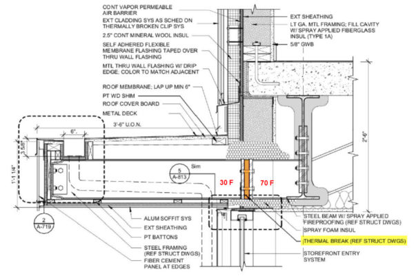
A thermal break is required to reduce heat loss at a canopy connection. The end plates in the connection are 12” x 12” and the thermal break material is 1” thick. The thermal conductivity of the thermal break material is given and we will assume that the temperature on the outside surface of the thermal break is 30 degrees and on the inside surface, 70 degrees.
T1 = 30 F, T2 = 70 F so ΔT = 40 F
t = 1”
k = 1.25 BTU/(hr/ft2/in/degrees F)
A = 1 ft2 (12” x 12”)
Q = 1.25 x 1(40/1) = 50 BTU/hr.
If we change the thickness from 1” to ½”, Q = 1.25 x 1(40/.5) = 100 BTU/hr. The heat flow is doubled.
Moreover, if we change the thickness to just ¼”, Q = 1.25 x 1(40/.25) = 200 BTU/hr. The heat flow increases by a factor of four.
The area of the thermal break is dictated by the structural design of the connection (end plate dimensions) so making a change in area to control heat flow (loss) through the thermal break is not a likely choice. The thermal conductivity of the thermal break is a fixed value based on the type of material and that varies slightly by manufacturer. For the materials currently available in the market, that are strong enough to meet structural requirements, the difference in this value is approximately 0.5 BTU/(hr/ft2/in/0F) – not enough to make significant changes in the heat flow through the connection.
To reduce heat loss due to thermal bridging, the thickness of the thermal break is the one variable that we can control to make an impact on the heat flow through the connection.
Transmittance and R value
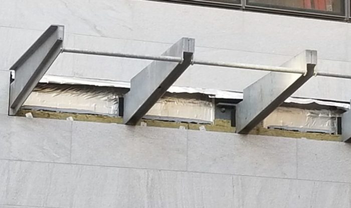
Thermal modeling has demonstrated that the R-value of a wall assembly can be reduced by more than half due to thermal bridging. In a steel connection such as a balcony or canopy, the thermal resistance of the wall is compromised by the transmittance or heat flow (loss) that is created by the beam passing through the exterior insulation, allowing internal heat to flow through the wall along the beam. A bolted steel connection is considered a point transmittance because it occurs at a single location, whereas a shelf angle for example, is described as a linear transmittance because it can be defined by a unit of length rather than a single location or point.
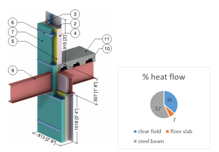
How much transmittance or heat loss can a beam through a wall create? In the example below (fig. 1), the nominal R-value of the wall assembly is R 29.2. This value is a function of all the thermal resistance values of all the materials in the assembly and any air film resistances. However, thermal bridging exists in three locations; the steel z girts, the floor slab and at the steel beam. In this article, we are addressing the steel connection only and will look at thermal bridging solutions for the steel z girts in a future post.
Fig. 1 (detail 5.7.2 Morrison Hershfield BETBG), through beam, no thermal break
The heat flow through the steel z girts, reduces the clear field R-value from 29.2 to an actual R-value of R 18.5. They are responsible for 36% of the heat loss in the wall. The R-value is further reduced to R 15.6 due to the linear transmittance of the floor slab. Finally, when we add the steel beam passing through the wall, the actual R value of the wall becomes R 6.9. Overall, there is a 68% decrease in the wall’s thermal resistance with the steel beam responsible for 57% of the heat loss. To reduce the heat loss due to the point transmittance at the beam, a thermal break can be installed in the connection.
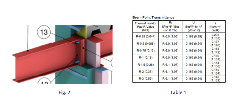
In figure 2., we have taken the same wall assembly and installed a ¼” thermal break in the steel beam connection. We then assigned a range of R-values to the thermal break to see how much the r-value of the wall would be improved. The range of R-values illustrate the effect that the thickness of the thermal break has on the results.
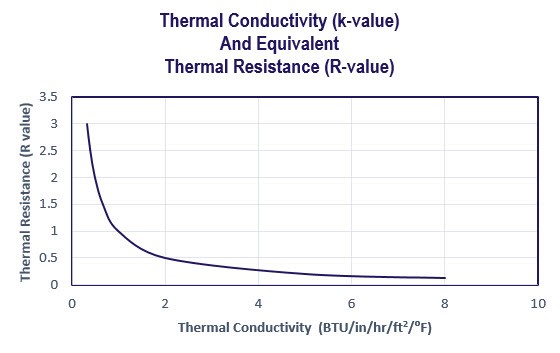
Note: thermal resistance or R-value is the inverse of thermal conductivity. To calculate the R-value of a thermal break material, just divide 1 by the thermal conductivity. R = 1/k
Important: If a thermal break material has a thermal conductivity of 1.25 BTU/(hr/ft2/in/0F), then its thermal resistance or R-value is R 0.8 per inch. Thus, if this thermal break is 3/4” thick, its actual R-value is R 0.6 and at just ½” thick, R 0.4 and so on.
Recall that the actual R-value of the wall went from R 15.6 to R 6.9 due to thermal bridging at the beam connection. The corresponding point transmittance (χ) or heat flow at the beam was 1.73. Table 1 shows the resultant point transmittance (heat flow) and effective R-value of the wall for a range of thermal break R-values using a ¼” thick thermal break.
The results show that even if you use a thermal break material with an R-value of 3 per inch, the heat flow due to the beam increases and the R-value of the wall decreases. In effect, the thermal break has made things worse. Why has this happened? How can the heat flow through the wall be worse with a thermal break than without?
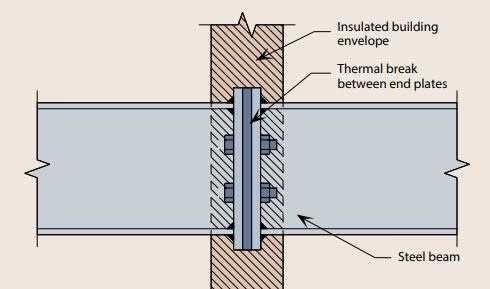
Image credit SCI
To incorporate a thermal break, an end plate on either side of the break in the beam is required. When we do this, we increase the contact surface area of the steel. Without a thermal break, we would be making the heat flow through the beam worse. With a thermal break, we need to acknowledge that the conductance of the thermal break material is a function of its thickness and the heat flow through the now thermally broken connection is a function of that, plus the area of the connection. (continued in part 2 of “Thermal Bridging in Steel Connections”)

References
Morrison Hershfield, Building Envelope Thermal Bridging Guide, v 1.4
Morrison Hershfield, ASHRAE 1365-RP, “Thermal Performance of Building Envelope Construction Details for Mid and High-Rise Buildings”, 2011

