Structural thermal break materials are used to reduce the heat loss associated with thermal bridging in steel connections that pass through exterior insulation. They can also reduce the risk of condensation forming within the wall as the heat loss cools material surfaces to below the dew point. In part two of this article, we discuss how thermal break materials used in steel connections help to keep material surfaces above the dew point as well as their role in helping to meet energy code requirements.
- Thickness and R value
- Condensation Risk
- Energy Code
Thickness and R-Value
If the thermal break is too thin, the impact of making the break is lost due to the increase in area of the highly conductive steel. Modeling of several thermal break materials has shown that when using thermal break materials, the thickness should be at least 1” to achieve any significant reduction in heat loss. This of course does vary by application and assembly.
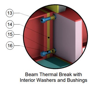
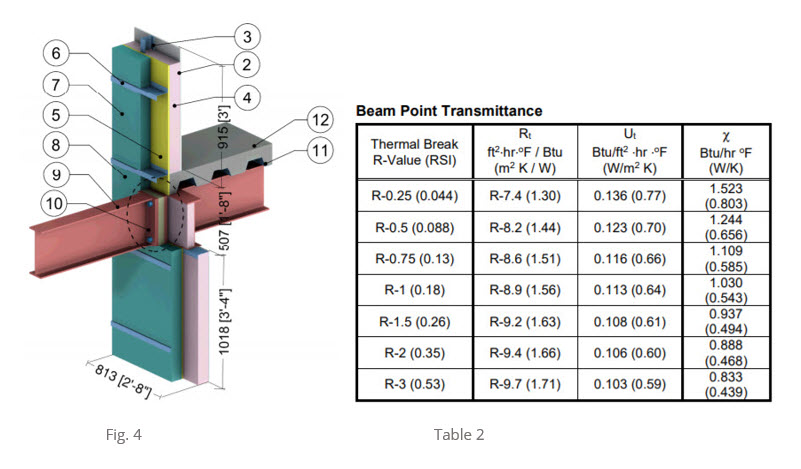
The model in figure 4., is the same wall assembly. This time however, the thermal break in the steel beam connection is now 1” thick and the same range of R-values are applied. Thermal break washers and bushings are also used around the bolts on the “warm” or inside of the connection1
1 Thermal break washers used under the bolt head and bushings used around the bolt shaft within the inside end plate reduce heat loss in the connection further by reducing conductive and convective heat flow through the bolts. In this model, the increase in wall R-value was R 0.8.
Condensation Risk
While a properly designed thermal break will reduce heat loss, thermal break materials are also effective at keeping steel connection surfaces above dew point temperatures. This is particularly important for connection details in buildings where higher than normal relative humidity values exist (hospitals or natatoriums) or in the Southern part of the United States where exterior humidity levels are higher.
A risk of condensation is also possible if the material surfaces within the wall assembly fall below the interior DP temperature in colder climates. Condensation can be avoided by ensuring the temperatures at the back plane of the exterior sheathing are warmer than the interior air dewpoint temperature. A thermal break in a steel canopy or balcony connection that is located in the proper position within the wall, will keep material surfaces warm and reduce condensation risk.
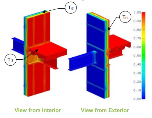
The results of the thermal models discussed in part 1 of this article also include thermal data sheets. These sheets provide surface temperatures of assembly components that could be exposed to interior air to help locate potential areas of risk for condensation. The temperatures are non-dimensionalized on a scale from 0 to 1 so that they can be used in a temperature index in order to be applicable for any climate (varying indoor and outdoor temperatures).
Image source: Thermal Bridging Solutions Library
Note: Many factors can affect the formation of condensation that are not included in the modeling (i.e, air leakage, diffusion, etc.) For more discussion, see section 5.3 of ASHRAE 1365-RP.
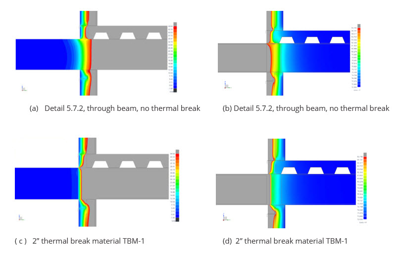
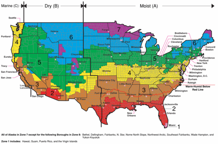
To see how effective a thermal break material can be at reducing potential condensation risk, we applied specific climate boundary conditions to the model wall assembly. Two versions of the model were used; detail 5.7.2 from the BETBG v, 1.4 (no thermal break) and the model using 2” thick thermal break material TBM-1, with an R-value of R 1.4 (0.7 per inch).
The following “dewpoint” analysis consisted of applying the climate boundary conditions to the models and removing all temperatures that fell above the dew point temperature. In order to indicate where there could be a possible risk for condensation to develop, only temperatures on material surfaces that were below the dewpoint temperature remained. It is important to note that this is a steady state analysis or “snap shot” of the models meant to indicate potential moisture issues. A hygrothermal analysis is a more accurate, dynamic analysis which considers heat and moisture transportation including air leakage in the wall assembly.
Cold Climate Design Conditions Hot-Humid Climate Design Conditions
(Chicago, Climate Zone 5) (Houston, Climate Zone 2)
Interior Temperature: 70oF Interior Temperature: 72oF
Interior Relative Humidity: 40% RH Interior Relative Humidity: 50% RH
Exterior Temperature: -1.5oF Exterior Temperature: 95oF
Exterior Relative Humidity: 71% RH Exterior Relative Humidity: 75% RH
In detail (a), Chicago, we can see that without a thermal break, temperatures below the dew point temperature exist on the inside of the external sheathing both along the steel beam and at the steel z-girt attachment locations. In detail (c) the thermal break pushes the dew point temperature outside of the external sheathing reducing condensation risk within the wall. The steel z-girts still present a risk.
In detail (b), Houston, we see cooler temperatures on the interior surfaces beyond the external sheathing that are below the dew point. If the air barrier is located on the exterior surface of the sheathing, this could pose a problem. In detail (d) the thermal break helps keep the steel beam surfaces that are below the DP temperature behind the air barrier.
Energy Code
Image Source: ASHRAE
Ultimately, the objective when using thermal break materials is to reduce heat loss, improve effective R-value and meet or exceed energy code requirements. Prescriptive R value requirements only consider the nominal R value of internal and external insulation without regard to the reduction caused by thermal bridging. And, we have seen that nominal R-values can be reduced over 50%.
Performance based, minimum U value requirements for wall assemblies are a more accurate and responsible design method because they acknowledge the effects of thermal bridging. Thermal break materials used in bolted, steel connections have been shown to be effective if designed properly. The thermal modeling results discussed in this article reveal that a 25% increase in R value, and a nearly 50% decrease in heat loss (point transmittance) are possible. Further, it was demonstrated that thermal break materials can be effective at keeping material surfaces within the wall assembly above the critical dew point temperature – especially in colder climates.
Using a 2” thermal break in the beam connection increased the effective R-value of the wall to over R-9 from R-6.9. R-9 represents an effective wall assembly U -value of U=0.11 (U=1/R). How does this compare to performance-based energy code requirements?
ASHRAE 90.1, 2013/2016 Minimum U value Requirements For Steel Stud Walls
The wall model inclusive of the thermal break meets only the requirement for climate zone 1. The internal batt insulation has a nominal R-value of R 12 and the exterior insulation is R 15. Remember that the steel beam was responsible for the largest amount of heat loss, but the steel z-girts also created significant thermal bridging. There are several other changes we can make to the wall assembly to improve performance.
For example, if we replace the steel z girts with thermally broken, composite Z girts, the effective R value of the wall becomes R 14.8 (U=0.067). Now the wall has nearly met climate zone 4. If we add exterior insulation increasing the nominal value to R 25, the effective R value of the wall becomes R 18.9 (U=0.053) and so on. Addressing both sources of thermal bridging and adjusting the R-value of the exterior insulation is necessary to improve the thermal resistance of the wall assembly. No amount of external insulation can be added to the wall to meet energy code requirements if we address only the steel z girts, and the steel beam has no thermal break and vice versa.
This article was written to assist architects and designers in making design decisions and to increase dialogue within the AEC community about thermal bridging in steel connections. Thermal break materials are necessary when designing to performance standards. It is important to note that the example used in this article was only one of many possible interface details. It was chosen to demonstrate how thermal break materials can help reduce the effects of thermal bridging in a steel connection.
About the author: Rob Haley developed the first thermal break material used for steel connections (Fabreeka-TIM) in 2012 while engineering manager at Fabreeka International. He was later co-owner of Armadillo NV where he was responsible for the marketing and research and development of Armatherm thermal break materials. He has over 10 years experience with thermal breaks to reduce heat loss due to thermal bridging. email: rob@thermalbridgingsolutions.com

Morrison Hershfield, Building Envelope Thermal Bridging Guide, v 1.4
ASHRAE 90.1, “Energy Standard for Buildings Except Low-Rise Residential Buildings”, 2010-2019.
Building Science Corporation, BDS-163, Straube, 2011.

